An improved version of my previous creation. Better and hackier!
This article is Part 2 in a 2-Part Series.
- Part 1 -More blinking LEDs - KITT inspired gizmo, version 1
- Part 2 -KITTBlink2 - KITT inspired gizmo AKA Larson scanner, version 2
Not a perfect desing
I shall mention beforehand, that this is not the best solution to the problem: “Making a Larson scanner without micro-controller”. Some people suggested using a counter and some logic gates (or diodes) - one of the possible solutions is explained in this Reddit comment. If a counter is used, the starting sub-circuit is not necessary, and therefore the resulting circuit is simpler and more reliable. I just decided to finish a design with the original idea (using shift registers) and to solve all the challenges.
Solving problems
A simple circuit shown in the previous post had some problems I wanted to remove:
- The first and the last LEDs were turned on twice each time the direction was reversed.
- It required a manual starting pulse.
- LEDs were just blinking. There was no cool fading trail effect.
Keep in mind that I am not an electronics engineer. My solutions are based on my limited knowledge, the information I was able to find online, and a trial-error driven fiddling.
Problem #1 - double flash
This one was easy to solve. I used 9 diodes instead of the original 8. First and last diodes are connected directly to shift registers and only the 7 remaining (middle) LEDs are driven by OR gates. As the active bit travels through the shift registers, it activates diodes on edges only once.
Problem #2 - starting the circuit
I figured out a circuit, that sends one pulse when the whole gizmo is powered on. It’s based on a 555 timer IC and its core is the good old mono-stable circuit.

The transistor Q2 brings C2 to ground when the circuit is powered on and that creates a pulse that triggers the mono-stable. One pulse is sent into shift registers and becomes a “travelling” pulse.
It’s not perfect, though. The length of a pulse which comes from mono-stable must be compatible with the clock frequency. Otherwise, it may fail to start the circuit or send more than one bit to shift registers.
Problem #3 - fading LEDs

I wanted badly this disappearing trail effect that the original KITT had.
That basically meant finding a way how to add a capacitor, charge it quickly and discharge slowly. I ended up with the following circuit.

The fadeout effect is created by components C1, R2, R3 and Q1. Resistance and capacity values control the duration of the fadeout effect. Diode D1 is there to prevent discharge through a grounded pin of a controlling IC. Resistor R1 is there to limit charging current to C1 and therefore to protect controlling ICs.
Complete circuit
The whole circuit can be divided into four blocks.

I already covered KICK-OFF and fade circuits (D1 - D9). There is also a standard clock based on a 555 timer, nothing special there.

And finally the driver. This time I used 74HCT4094 shift registers. Mainly because their pin-out was easier to wire together with 74HCT32 OR gates.

It’s a bit tricky to parse what is connected to what, but in the end, it’s simple. There are 2 shift registers in series (and in a loop). They use only one clock signal for both CLK and STROBE inputs. Starting signal comes to the loop through a diode. Each shift register controls one diode directly and 7 in cooperation with the other one through OR gates.
You can find the whole schematic on EasyEDA.
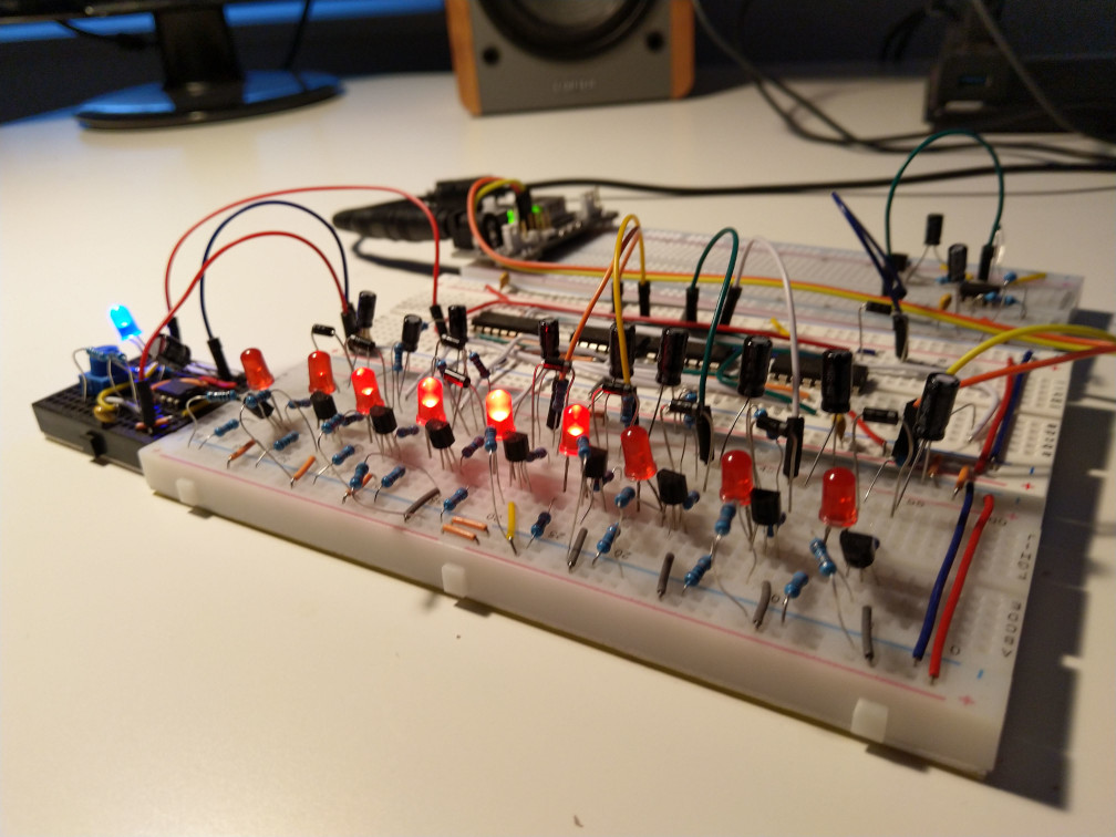
Prototype in action
Here is a short video (and you can watch it on YouTube too), isn’t it cute?
The fade-out effect is less visible on the video than in real life.
And finally one static image from the top.

What’s next?
I am going to move this thing onto a perf-board and perhaps create some improvised enclosure for it. I’ll post result once it’s done.
Update
I learned on Reddit that this effect actually has name - Larson scanner (after Glen A. Larson who produced the Knigth-Rider and the Battle Star Galactica series).
Bill of materials
I was asked for a BOM, so here it is:
| Designator | pcs | Part |
|---|---|---|
| D1 | 9 | FR107 |
| R1,R4 | 18 | Resistor 330 |
| R2 | 9 | Resistor 2k2 |
| R3,R6,R8 | 11 | Resistor 100k |
| Q1 | 9 | NPN Transistor BC337 |
| LED1 | 9 | LED 5MM red |
| C1,C3 | 10 | Electrolytic cap 10uF |
| R5 | 1 | Resistor 1M |
| R7 | 1 | Resistor 30k |
| C2 | 1 | Electrolytic cap 0.47uF |
| Q2 | 1 | NPN Transistor 2N3904 |
| U1,U2 | 2 | NE555P |
| C4,C6 | 2 | Ceramic cap 0.01u |
| C5 | 1 | Electrolytic cap 0.22uF |
| R9 | 1 | Resistor 1k |
| R10 | 1 | Resistor 2k |
| R11 | 1 | Potentiometer 10k |
| U3,U4 | 2 | 74HCT4094N |
| U5,U6 | 2 | 74HCT32N |
| D2 | 1 | 1N4007 |
A few notes to the BOM:
- Most of the components (resistors, diodes, capacitors, transistors) are from cheap sets from Aliexpres. You can choose any general purpose diode and I suppose transistors can be replaced too.
- Integrated circuits - I used
HCTversions, but I think it should work with other variations too. It’s also possible to use another shift registers (e.g.sn74hc595) and/or OR gates (but obviously they will have different pin-outs and so on)
This article is Part 2 in a 2-Part Series.
- Part 1 -More blinking LEDs - KITT inspired gizmo, version 1
- Part 2 -KITTBlink2 - KITT inspired gizmo AKA Larson scanner, version 2